Ying Wang, Zewei Yuan, Tianzheng Wu,and Heran Yan
ABSTRACT The effects of the nonuniform cutting force and elastic recovery of processed materials in ultra-precision machining are too complex to be treated using traditional cutting theories,and it is necessary to take account of factors such as size effects,the undeformed cutting thickness,the tool blunt radius,and the tool rake angle.Therefore,this paper proposes a new theoretical calculation model for accurately predicting the cutting force in ultra-precision machining,taking account of such factors.The model is firs used to analyze the material deformation of the workpiece and the cutting force distribution along the cutting edge of a diamond tool.The size of the strain zone in different cutting deformation zones is then determined by using the distribution of strain work per unit volume and considering the characteristics of the stress distribution in these different deformation zones.Finally,the cutting force during ultra-precision machining is predicted precisely by calculating the material strain energy in different zones.A finit element analysis and experimental data on ultra-precision cutting of copper and aluminum are used to verify the predictions of the theoretical model.The results show that the error in the cutting force between the calculation results and predictions of the model is less than 14%.The effects of the rake face stress distribution of the diamond tool,the close contact zone,and material elastic recovery can be fully taken into account by the theoretical model.Thus,the proposed theoretical calculation method can effectively predict the cutting force in ultra-precision machining.
KEYWORDS Ultra-precision cutting,Diamond tool,Cutting force,Strain energy,Finite element analysis
Ultra-precision machining technology is increasingly being used in the production of components with high accuracy and good surface integrity in aerospace,military,optical,mechanical,electronic,and other high-tech applications.The machining parameters are very important for the cutting quality of the workpiece in ultra-precision machining processes.However,many of the classical theories that are applicable to the traditional cutting process cannot be used for ultra-precision machining,because they are unable to explain many of the new phenomena that arise.It is therefore necessary to develop a new cutting theory to provide a basis on which to optimize the parameters of ultra-precision machining.The cutting force is a key physical parameter used to monitor the cutting process,since it can reflec the heat generation,tool wear,and quality of the machined surface during cutting.1Therefore,research on the cutting force is fundamental for achieving improvements in ultra-precision machining.
At the same time,size effects are also more significan in ultraprecision machining compared with the traditional cutting process.As the cutting size is reduced,the cutting tool starts to perform noncutting behaviors,such as squeezing,scratching,and ploughing of the surface of the workpiece.These lead to a deterioration in surface processing quality.To improve machining quality,it is necessary to analyze the machining characteristics of the cutting edge of the tool and the material being cut,as well as the interaction between them.
Diamond tools have unparalleled advantages for micrometer and submicrometer cutting owing to their high hardness,high strength,and high wear resistance.They have become the most important tools for ultra-precision machining.Yuanet al.2studied the influenc of the blunt circle radius of diamond tools on ultraprecision machining and concluded that this parameter determines the size of the minimum undeformed cutting thickness and the integrity of the machined surface.Yanet al.3established a model of the undeformed cutting thickness to predict the cutting force of diamond tools for processing single-crystal silicon and found that the average error between experimental and predicted results was less than 20%.Peng4used diamond tools to cut silicon carbide particle reinforced aluminum(SiCp/Al)composite materials.He considered the effect of the SiC particles on the aluminum matrix and proposed a theoretical cutting force model that accurately predicted the cutting force and the turning time for SiCp/Al composites.The theory of ultra-precision machining proposed by Jing5lays a foundation for predicting minimum chip thickness in ultra-precision machining and also provides an improved constitutive model.Yuanet al.6used diamond probes to cut graphene and analyzed the influenc of different cutting directions on the cutting-edge energy and cutting force.Tianet al.7studied size effects on ultra-precision cutting by combining mechanism-based strain gradient(MSG)theory with the traditional Johnson–Cook constitutive model.They established a constitutive model for cutting oxygen-free copper at the mesoscopic scale,which further improved the accuracy of finit element simulation of ultra-precision cutting.
There has been insufficien theoretical analysis of ultraprecision machining at the submicrometer and nanometer scales,at which the nonuniformity and crystal boundaries of workpiece materials have a significan influenc on the cutting force.It is therefore necessary to establish a cutting model that takes account of the material structure.The finit element method is suitable for analyzing cutting characteristics at most of the scales associated with ultra-precision machining and can simulate the actual cutting process more accurately than other methods.However,ultra-precision machining extends down to the nanometer scale,which is smaller than the submicrometer lower limit for the applicability of finit element analysis,and in the case of nanometer cutting,analyses need to be performed from the perspective of molecular dynamics.The strongly nonlinear characteristics of the cutting process mean that simulations converge easily,but the complexity of the process imposes a considerable computational burden,and calculation times are long.
For accurate modeling of the ultra-precision cutting process,it is necessary to develop a new theoretical calculation method.In this paper,through an analysis of the material stress–strain relationship,a versatile ultra-precision cutting model based on the strain energy method is proposed.The strain energy calculation for each deformation zone is simplified and the cutting force in ultra-precision machining can be predicted efficientl and precisely.
From the energy dissipation model described in Ref.8,it can be seen that there are three main forms of energy dissipation in the cutting process.These correspond to the three main sources of cutting force.In contrast to ordinary cutting,in ultra-precision cutting,the entire cutting deformation zone can be divided into three parts:a plastic deformation zone,a friction deformation zone,and an extrusion deformation zone,also termed the first-deformatio zone,second-deformation zone,and third-deformation zone.In this section,the strain energy is analyzed for each of these three deformation zones,and then,based on the energy method,calculational formulas are derived for describing ultra-precision cutting of plastic materials.
Chip formation is a process of material yielding deformation.According to the Holloman equation,the material stress–strain curve can be expressed as
whereσis the real stress of the material,εis the real strain of the material,τis the real shear stress,γis the real shear deformation,Kσis the material shear-hardening coefficientKτis the material work hardening coefficient andnis the material work hardening index.Kσ,Kτ,andnare all constants,which are obtained from tensile testing.Equation(1)can be rearranged as follows:
The differential method is used to calculate the strain plasticity of the workpiece material in the cutting process.Equation(3)is applied to the small displacements between the small elements of the stressed material and integrated.Thus,the strain energyEper unit volume is given by
When Eq.(3)is substituted into Eq.(4)and the integration is performed,the strain energyEσper unit volume of the machined material8is obtained as
The total plastic strain energy of the machined material can be obtained by integrating over the material strain volume.Thus,the normal strain energyWσof the material8is given by
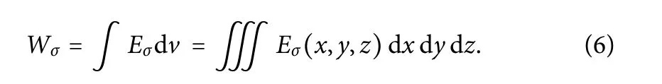
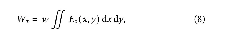
To simplify the calculation,the cutting width is regarded as a constantw,and the three-dimensional plastic strain process during cutting is simplifie to a two-dimensional plastic strain process.Thus,

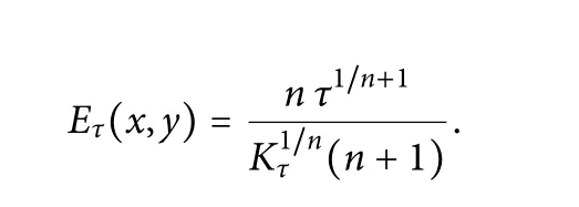
Similarly,the shear strain energyWτof the machined material can be obtained as
where
According to slip-line fiel theory,the chip deformation zone can be divided into three deformation zones,4as shown in Fig.1.
These three deformation zones appear near the cutting edge,and the stress concentration in different deformation zones is very complicated.Because different types of materials differ greatly in their deformation behavior and the associated internal mechanisms,the interactions of the processed materials with the tool are also different.In particular,when the cutting size decreases to the nanometer level,the behavior of the material itself depends on the arrangement of atoms and the related characteristics of the crystal structure.The force on the machined material can be divided into normal stress and shear stress.The cutting layer is separated from the workpiece matrix,most of which becomes chips,with a small part remaining on the machined surface.The following subsections present analyses of the stress distribution characteristics of the different cutting deformation zones.
A.First deformation zone
In the firs deformation zone,the main form of strain to which the material is subjected is shear displacement,and most of the deformation zone is formed by chips.To analyze the shear strain process in the deformation zone,the continuous shear strain is divided into slices to give a discretized shear strain model,and it is assumed that the shear stress is uniformly distributed in each slice,as shown in Fig.2,whereφis the shear angle,γ0is the rake angle of the tool,bis the slice thickness,his the undeformed cutting thickness,δis the tool displacement corresponding to the slice,andξis the displacement of the tool in thexdirection.
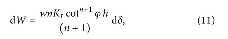
With the coordinate system established as shown in Fig.2,the internal strain energy dWof each slice can be obtained from Eq.(8)as
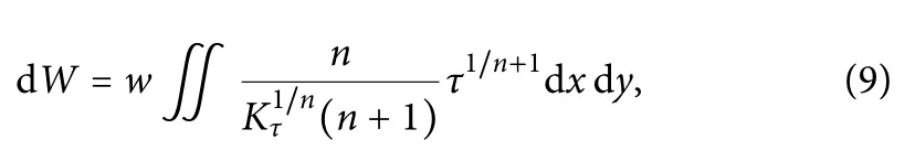
i.e.,
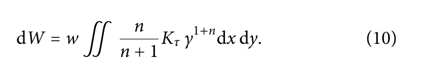
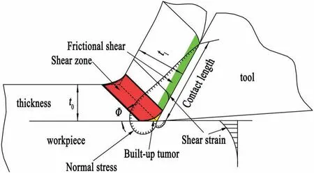
FIG.1.Geometric relationships of the cutting process.

FIG.2.Strain zone of the first deformation zone.
In the study by Atkins,10the shear strain was taken to be equal to the ratio of the slice thicknessbto the displacementξin thexdirection.11The length of the slice can be sorted out as
Performing the integration in Eq.(11) gives the total strain energyW1of the firs deformation zone as
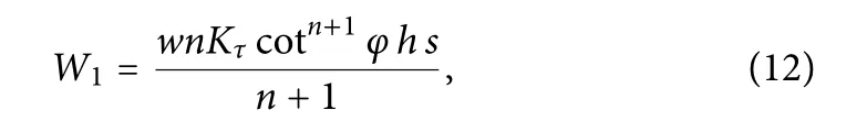
wheresis the total displacement of the tool in the cutting direction.
B.Second deformation zone
In the second deformation zone,the chips and the rake face of the tool continue to squeeze and rub,with the result that the chips close to the rake face of the tool are fibrillated and the chips become parallel to the rake face of the tool.In most cutting force calculations,the tangential and normal forces on the tool are regarded as being uniformly distributed.12However,photoelastic measurements of diamond too during the cutting process show that the stress distribution on the tool surface is uneven.The greatest stress occurs at the tool tip,and the surface stress decreases to zero at the end of the chip–tool interface.13To describe this variation in cutting force,the direction of chip movement is taken as the positive direction of thexaxis,and a coordinate system is established such that the stress on the rake face of the tool changes withx,as shown in Fig.3,14whereαis the tool clearance angle,lpis the close contact length,lcis the total contact length,andμis the sliding friction coefficient
Considering the stress distribution in Fig.3,McClainet al.15modeled the normal stressσnon the rake face of the tool as the following power function:
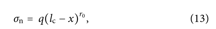
wherexis the distance between the separation point of the chip and the rake face of the tool,qis the stress distribution coefficient andr0is the stress distribution index.qandr0are constants obtained from dynamometer measurements.
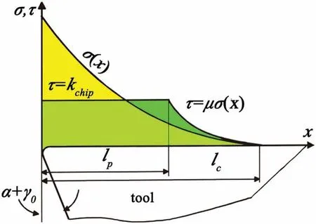
FIG.3.Stress distribution on the rake face of the tool.
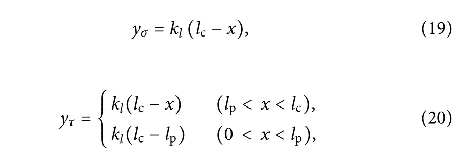
When the normal stress is low,there is ordinary friction between the tool and the chip,and the tangential stress can be obtained as the product of the normal stress and the friction coefficient However,when the normal stress increases,the tangential stress of the material will eventually reach the shear yield stress.It will then cease to increase,with the formation of a stress platform.At this time,the chip and the tool surface are in close contact,and there is little relative slipping.The tangential stress distribution on the tool rake surface can then be expressed as
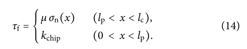
The expressions forlcandlpare as follows:
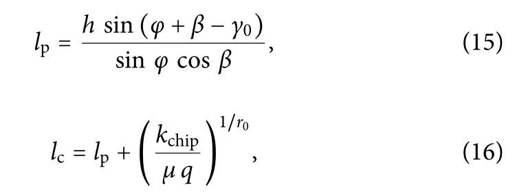
wherekchipis the ultimate shear stress of the material,andlphas a certain proportional relationship withlc.The value of the ratioλ=lp/lcis related to the tool and workpiece material and is generally in the range 0.50–0.75.
To analyze the strain volume,the normal strain and the tangential strain need to be discussed separately.According to slip line fiel theory,16the normal and tangential strain zones can be simplifie as triangles and trapezoids,as shown in Fig.4.
At timet0in Fig.4(a),the chip extrusion strain zone in front of the tool isOAB.As the tool moves a distanceδin the cutting direction,OABmoves backward relative to the tool,toO′A′B′.The total strain zone isOABplusABB′A′.In the same way,it can be considered that the shear strain zone in Fig.4(b) moves fromOABCtoO′A′B′C′,and the total strain zone isOABCplusBCC′B′.The infinitesima elements inABB′A′andBCC′B′can be regarded as integrals corresponding toOABandOABCin thexdirection,and do not change withx,and thus
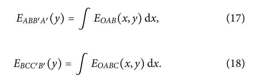
According to the geometric relationships in Fig.4,ABandABCcan be described by the following functions ofx:
wherekl=hsin(90 −γ0)/[lc−hcos(90 −γ0)]is the slope ofAB.Substitution of Eqs.(13)and(14)into Eqs.(7)and(8),respectively,gives

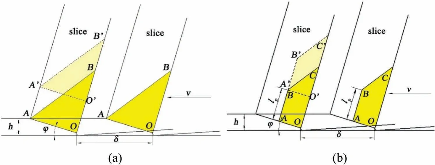
FIG.4.Strain zones of the second deformation zone:(a)normal stress–strain zone;(b)tangential stress–strain zone.
In a stable cutting process,OABandOABCwill remain stable.However,ABB′A′andBCC′B′will gradually increase with the movement of the tool,and a discretization analysis of slices gives
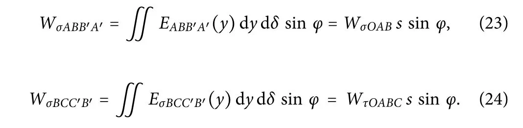
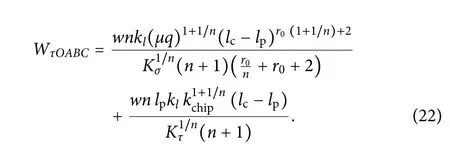
Therefore,the total strain energyW2of the chip–tool interface interaction can be derived as

C.Third deformation zone
Owing to the blunt radius of the cutting tool,the flan surface of the tool wears partially.This intensifie the extrusion friction on the workpiece,causing deformation and rebounding of the workpiece.The crystal grains become elongated and fibrillated The force on the blunt zone of a cutting tool is called the plowing force.This zone is formed by the machined surface,which determines the processing quality of that surface.The material is subjected to normal stress and yields,and its contact surface will also exhibit relatively large sliding.However,the material still has elastic characteristics after yielding,and so there will be a certain recovery phenomenon after the tool is drawn,which needs to be analyzed,as shown in Fig.5.
In Fig.5,hcis the minimum undeformed cutting thickness,heis the elastic recovery of the material,and the elastic recovery ratepeis 0.3.PointAis the point where the material has no sliding relative to the tool.The material above pointAforms chips upward relative to the sliding direction of the tool,corresponding to the firs deformation zone.The material below pointAforms the machining surface downward relative to the sliding direction of the tool.The zoneOACDis decomposed intoOACandODE.The direction of movement is the cutting direction.17
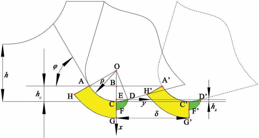
FIG.5.Strain zone of the third deformation zone.
To conduct a stress distribution analysis,the zoneOACcan be simplifie as a two-dimensional cylinder.In this cylinder,the stress distribution of the material under the pressing action becomes uniform owing to the plastic flo of the material.The contact stress distribution on the surface of the cutting tool can be regarded as approximately uniform and perpendicular to the contact surface.The magnitude of the normal stressPon the contact surface is related to the amount of indentationΔand expressed as17
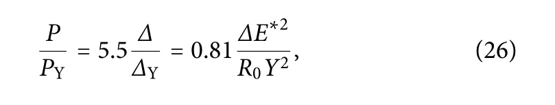
whereR0is the comprehensive radius of curvature when the arc is in contact with the planeR=r.The contact width of the zoneOCDis denoted bya′and the angle ∠DOEis denoted byη.In Eq.(26),PYdenotes the stress when yielding begins and is given by
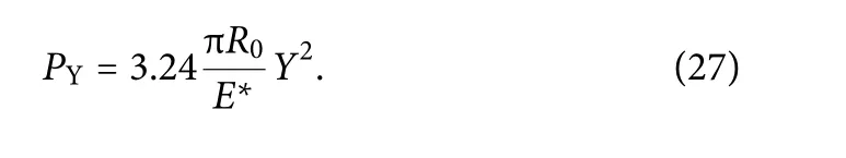
Combining Eqs.(26)and(27)gives
In these equations,E*is the comprehensive modulus of elasticity and is given by
whereE1andE2are the elastic moduli of the cutting tool and the workpiece material,respectively,andν1andν2are the Poisson’s ratios of the cutting tool and the workpiece material,respectively.The amount of indentationΔcan be expressed asΔ=a2/2R,whereais the contact width andris the radius of the cutting tool blunt circle.
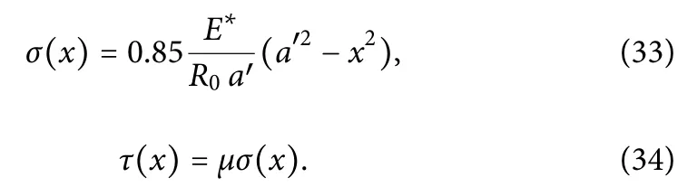
The relative sliding process between the zoneOACand the material can be considered as close contact relative sliding.Also,the surface tangential stress is uniformly distributed.Its direction is the tangent direction of the contact surface.Taking pointOas the origin,a polar coordinate system is established in which theOCdirection is the positive direction of the polar coordinate axis.The stress in the zone microelementACGHis
Calculations of the normal stressPcan be found in the literature.17Its direction is parallel to the vectorρ,while the direction of the tangential(shear)stresskchipis perpendicular toρ.
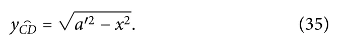
According to studies of contact mechanics,the strain zone generated by indentation starts from the initial contact point.The strain zone is approximately radial,accompanied by an approximately circular strain shape.ACGHtakes the form of an arc of a ring,the center of which coincides with the centerOof the tool blunt circle.The inner radius of the arc is the cutting tool edge radiusrand its outer radius isR.The ratio ofRto the contact widthais constant through the press-in experiment(R/a=3).At the same time,the direction of tool movement is parallel to the cutting surface,and the contact widthais taken as the tool blunt radiusr:a=r.The corresponding equations then become
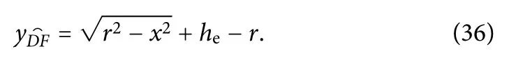
The zoneCDFin Fig.5 is the contact zone,which corresponds to elastic recovery of the material and is a purely elastic strain zone.The corresponding surface stress can be calculated using the Hertz contact equation.A coordinate system is established with pointEtaken as the origin,EFas the positive direction of thexaxis,andEDas the positive direction of theyaxis.The distribution of surface stress in thexdirection is then17
It can be seen from Eq.(32) that the shear force under ordinary contact follows the friction theorem.The corresponding elastic strain volume isCDF,and the equation is
This can be simplifie to an arc of a ring withEas its center,and the equation is
Substitution of Eqs.(30)–(32)into Eqs.(7)and(8)gives
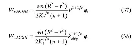
Substitution of Eqs.(33)–(36)into Eqs.(7)and(8)gives
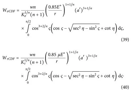
In these equations,Ϛis a dimensionless parameter.The strain energy in the zonesCGG′C′andCFF′C′also increases with the movement of the tool,and then
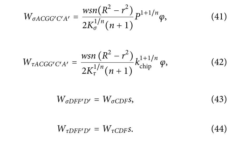
Therefore,the total strain energyW3of the interaction between the workpiece and the tool interface can be derived as

D.Total strain energy and cutting force
Combining the results for the strain energy in the three deformation zones obtained above,the total strain energyWduring the cutting process is

The total cutting force is
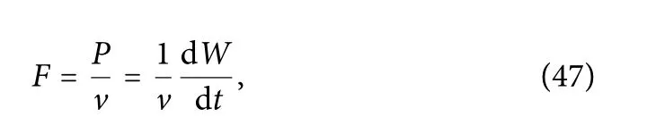
wherevis the cutting speed andtis the cutting time.
In this study,Cu and Al are considered as materials to analyze the influenc of different cutting parameters on the cutting force of diamond tools in ultra-precision machining.The single-variable control method is used to analyze four parameters:undeformed cutting thickness,cutting speed,tool blunt radius,and tool rake angle.
To determine the accuracy of the ultra-precision cutting force,the finit element analysis software Abaqus is used to simulate the cutting process according to the parameters in Table I.The simulation is mainly carried out using a combination of the adaptive grid method and the Johnson–Cook constitutive model.The equation of the Johnson–Cook constitutive model is7

whereA,B,C,n,andmare physical property constants,C,n,andmare dimensionless constants,σis the equivalent stress,εis the equivalent strain,is the dimensionless equivalent strain rateis the equivalent strain rate andis the reference strain rate),andT*=(T−Tr)/(Tm−Tr) is the dimensionless temperature (Tmis the melting temperature andTris the ambient temperature,whichis 20○C).The constantsA,B,C,n,andmfor Cu and Al are listed in Table II.

TABLE I.Cutting parameters.

TABLE II.Parameters of Johnson–Cook constitutive model.
The finit element analysis model is established,and twodimensional cutting simulations are performed.The cutting width is taken as 1 mm.The elastic parameters of Cu,Al,and the diamond tool material are shown in Table III.
The two-dimensional cutting simulation model is shown in Fig.6.This cutting model is suitable for a variety of tools.In view of the superiority of diamond tools and their wide application in ultraprecision machining,such a tool is considered in the model.The tool size is 0.5μm,the tool clearance angle is 5○,the thermal expansion coefficien is 1×10⁻⁶,the friction coefficien is 0.3,and the tool rakeangle and obtuse radius are as given in Table I.The unit size of the material to be cut is 0.1μm.The adaptive grid method is used for modeling.
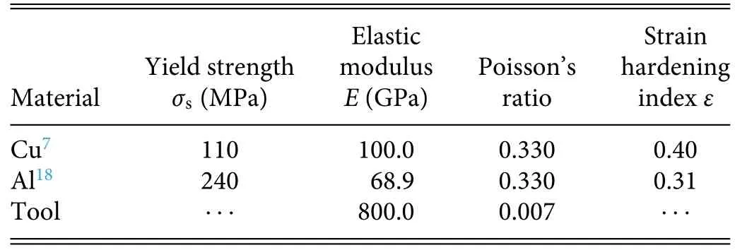
TABLE III.Parameters of workpiece and tool materials.
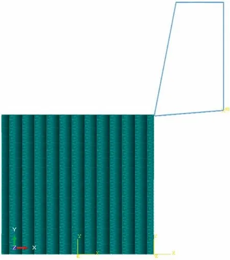
FIG.6.Two-dimensional cutting model.
The finit element simulation results for the cutting forces for Cu and Al materials under the influenc of various factors are compared with the results of theoretical calculations in Figs.7–14.It can be seen that both the simulated and calculated values of the cutting force depend on the undeformed cutting thickness of the material,the cutting speed,the cutting tool edge radius,and the tool rake angle.The mean relative errors in the cutting force under the influenc of the various factors are shown in Table IV.
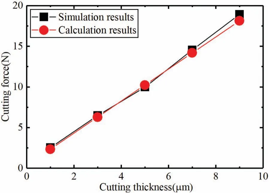
FIG.7.Variation of cutting force with undeformed cutting thickness during cutting of Cu.
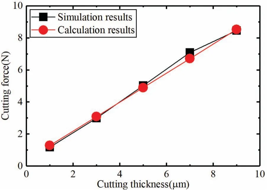
FIG.8.Variation of cutting force with undeformed cutting thickness during cutting of Al.
Owing to instabilities resulting from material fracture and crack propagation in the simulation process,the contact zone between the material and the tool varies,which affects the behavior of the cutting force,leading to some deviation between the results of the simulations and those of the theoretical calculations.
It can be seen from Figs.7 and 8 that the cutting force and the undeformed cutting thickness are more or less proportional.This is mainly because the strain volume in the firs deformation zone is proportional to the thickness.Therefore,the simulation model gives a better fi for the cutting forces for Cu and Al.
Figures 9 and 10 show that the simulation results for the cutting force for both Cu and Al fluctuat slightly when the cutting speed increases.However,the calculation results for the cutting force do not change.This is because a change in cutting speed causes the material damage limit in the simulation unit to fluctuate At the same time,the mean relative errors between the calculation and simulation results for both materials in Table IV are less than 5%,indicating that the cutting speed has a limited effect on the cutting force.
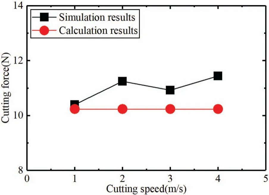
FIG.9.Variation of cutting force with cutting speed during cutting of Cu.
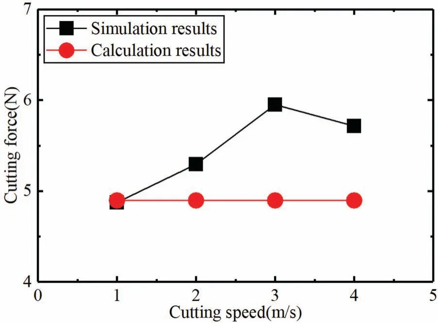
FIG.10.Variation of cutting force with cutting speed during cutting of Al.
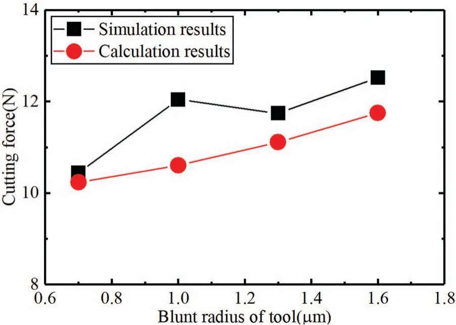
FIG.11.Variation of cutting force with cutting tool edge radius during cutting of Cu.
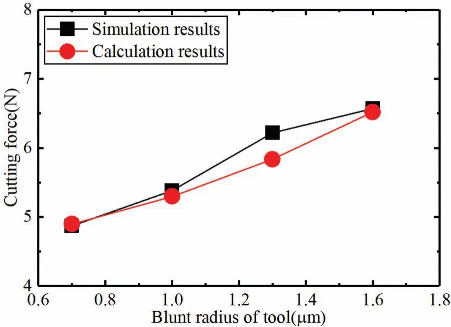
FIG.12.Variation of cutting force with cutting tool edge radius during cutting of Al.
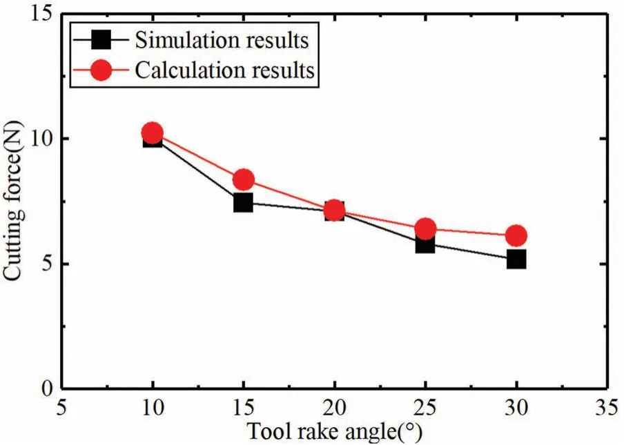
FIG.13.Variation of cutting force with tool rake angle during cutting of Cu.
Figures 11 and 12 show that when the cutting tool edge radius increases,the cutting force increases slowly and nonlinearly.This is because an increase in cutting tool edge radius will increase the extent of the plastic strain zone on the flan face,although the stress remains unchanged.By contrast,the stress in the elastic strain zone increases,but the extent of that zone remains unchanged.The material strain zone in the third deformation zone is small,and so there is only a slight increase in the cutting force.If the cutting tool edge radius is greatly increased,it will have a significan impact on the cutting force.
The results in Figs.13 and 14 show that the cutting forces for the two materials decrease greatly when the tool rake angle increases.This is because the cutting forces for Cu and Al are greatly affected by this angle.However,as shown in Table IV,the simulation and calculation results have large mean relative errors:10.14% and 8.41%.This is because the tool rake angle directly determines the shear strain in the firs deformation zone.At the same time,this angle affects the contact length between the shear angle and the tool rake face,thus leading to increased error.
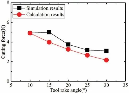
FIG.14.Variation of cutting force with tool rake angle during cutting of Al.
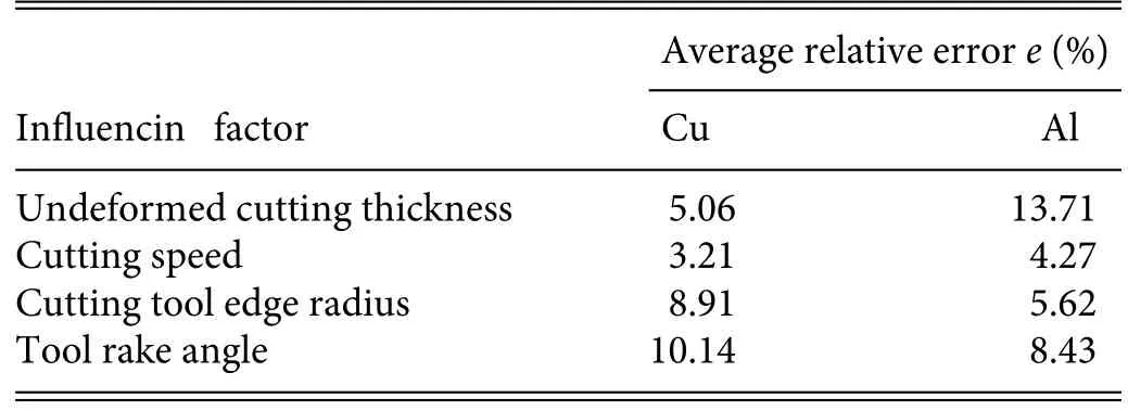
TABLE IV.Mean relative errors between calculation and simulation results for cutting force.
It can be seen from Figs.7–14 that there are fluctuation and deviations between the results of theoretical calculations and those of finit element simulations.However,the results from the methods exhibit similar trends under the influenc of various factors,indicating that the model presented here provides a good representation of the cutting force in ultra-precision machining.
Rahmanet al.19conducted ultra-precision cutting experiments to investigate the cutting force for Cu and Al.The simulations of the cutting force in the present paper are based on the same materials and cutting parameters as used by Rahmanet al.,and the simulation results are compared with their experimental results in Figs.15 and 16,which show the variation of cutting force with undeformed cutting thickness.19It can be seen that the cutting force increases when the undeformed cutting thickness increases.Under the same conditions,the cutting forces for Al and Cu are different,because the inherent material characteristics have a major effect on response characteristics in micromachining.As the undeformed cutting thickness increases,the cutting force for Cu increases quite rapidly,but the increase in the cutting force for Al is relatively slow.
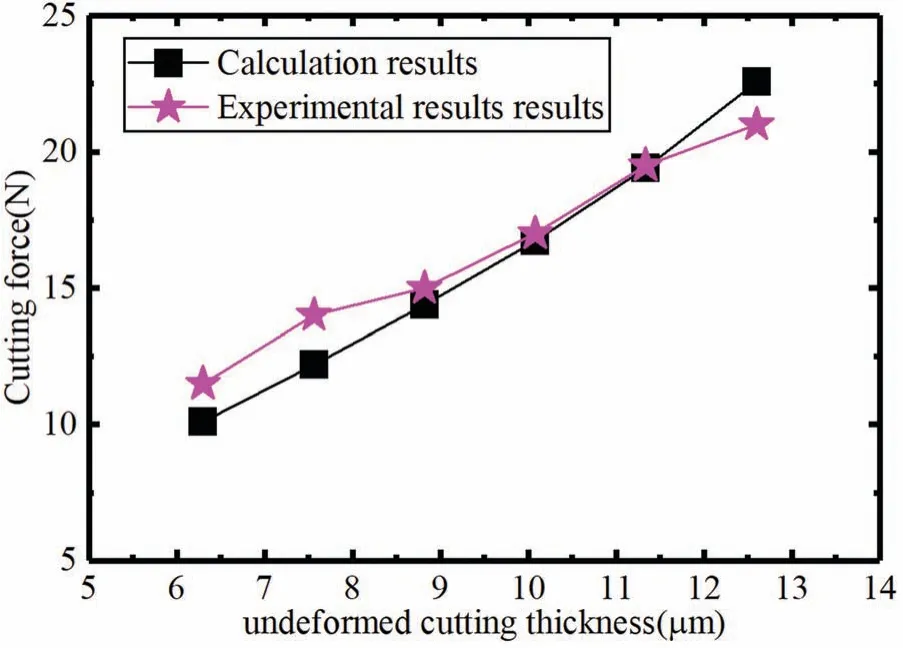
FIG.15.Comparison of calculation and experimental results for the variation of the cutting force for Cu with undeformed cutting thickness.

FIG.16.Comparison of calculation and experimental results for the variation of the cutting force for Al with undeformed cutting thickness.
From the above comparison,it can be seen that the calculation and experimental results show similar trends of variation of the cutting force with the cutting parameters,with the error being less than 8%.The actual cutting process will be affected by work hardening,material inhomogeneity,transmission error,cutting temperature,and other parameters,and so the stress distribution and strain zone in the actual cutting process cannot be obtained accurately,and cutting stability will also be affected.Error analysis shows that the error between the calculation and experimental results is small,and the method of calculating the cutting force based on strain energy can provide a reference for the prediction of cutting forces in ultra-precision machining.
The process of ultra-precision machining is very complex,involving multiple aspects.This paper has proposed a theoretical model to calculate the cutting force in such machining and has compared its results with those obtained from finit element simulations and from experiments.The significan finding of this study are as follows:
(1) In the case of ultra-precision machining,it is possible to calculate the cutting strain energy accurately by analyzing the strain volume and stress distribution in deformation zones.
(2) To accurately predict the cutting force in ultra-precision machining,it is necessary in the contact analysis of the tool rake face to consider the close contact zone between the diamond tool and the chip and to take account of the nonuniform stress distribution.
(3) The strain zone generated by the flan face of the diamond tool is small and has limited influenc on the cutting force,and it can be ignored under appropriate conditions.
(4) The rake angle of the diamond tool has a very strong influ ence on several parameters in the cutting force analysis,which increases the uncertainty in the cutting and makes the cutting force fluctuat greatly,but the overall calculation results are still consistent with the simulation results.
The cutting force calculation method proposed in this paper is versatile and has good accuracy for Cu and Al.The calculation model can be adapted to the different micrometer-level cutting depths in ultra-precision machining and can provide a basis for the setting of ultra-precision machining parameters.
ACKNOWLEDGMENTS
This work was supported by the National Natural Science Foundation of China (Grant No.51305278),the Liaoning Revitalization Talents Program,China(Grant No.XLYC2007133),and the Natural Science Foundation of Liaoning Province,China(Grant No.2020-MS-213).